
Modification of the pump characteristic curve
Question, remark ? Contact us at contact@myengineeringtools.com
| Section summary |
|---|
| 1. Definition |
| 2. Change of speed |
| 3. Change of impeller diameter |
| 4. Changes due to viscosity |
| 5. Interactive Affinity Laws Calculator |
1. Definition
The pump characteristic is an essential tool in selection and troubleshooting of pumps. It gives the performance of the pump by plotting, on a same graph :
- The pump Head \(H\) (m)
- The pump efficiency \(\eta\) (%)
- The \(NPSH\) (m)
- The power \(P\) (kW)
As a function of the flow rate \(Q\) (m3/h)
However, it happens often in industrial environment that the pump characteristic is available in certain conditions (pump rotation speed, diameter of the impeller). It can be very useful to be able to approximate the head or capacity that would be experienced by changing one parameter.
Please note that the method presented is an approximation. For detail design, the pump characteristic in the design conditions is required.
⚙️ Interactive Pump Affinity Laws & Modification Calculator
Calculated Operating Performance
💡 Industrial Best Practice: Pump Modification & Affinity Law Limits
- Impeller Trimming Limits: Affinity laws assume strict geometric similitude. When trimming an impeller, only the outer diameter is reduced while vane width and casing geometry stay identical. Limit trims to ≤ 10% to 15% of original diameter. Trimming over 20% severely increases cutwater clearance, generates high recirculation eddies, and drastically reduces hydraulic efficiency.
- Speed Variations via VFD: When slowing down a pump, minimum speed is commonly bounded at 30 Hz (~60% of base speed) to ensure motor cooling fan effectiveness and avoid settling in slurries or operating below minimum continuous stable flow (MCSF).
- NPSH Required Behavior: Remember that \(NPSH_R\) scales approximately with the square of speed: \(NPSH_{R2} \approx NPSH_{R1} \times (RPM_2 / RPM_1)^2\). Increasing speed sharply increases risk of cavitation!
- Motor Overload Hazard: Increasing speed by just 10% increases absorbed brake horsepower by approximately \((1.10)^3 = +33.1\%\). Always verify motor nameplate rating before turning up pump RPM.
2. Change of speed
The change of head when changing the rotation speed can be approximated the following way :
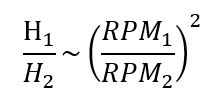
Equation 1 : Approximation of change pump head when change pump speed
H1 = pump head in reference conditions (m)
H2 = pump head in new conditions (m)
RPM1 = reference rotation speed (rpm)
RPM2 = rotation speed in new conditions (rpm)
The change of capacity when changing the rotation speed can be approximated the following way :
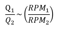
Equation 2 : Approximation of change of pump capacity when change pump speed
Q1 = pump capacity in reference conditions (m3/h)
Q2 = pump capacity in new conditions (m3/h)
RPM1 = reference rotation speed (rpm)
RPM2 = rotation speed in new conditions (rpm)
3. Changes of impeller diameter
It is possible to have an idea (very approximate) of the change of head when changing the impeller diameter at constant speed thanks to the following relations :
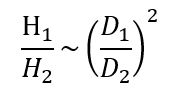
Equation 3 : Approximation of change pump head when change pump impeller diameter
H1 = pump head in reference conditions (m)
H2 = pump head in new conditions (m)
D1 = reference impeller diameter (m)
D2 = new impeller diameter (m)
The change of capacity when changing the impeller diameter can be approximated the following way :
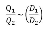
Equation 4 : Approximation of change of pump capacity when change pump impeller diameter
Q1 = pump capacity in reference conditions (m3/h)
Q2 = pump capacity in new conditions (m3/h)
D1 = reference impeller diameter (m)
D2 = new impeller diameter (m)
4. Changes in pump characteristic due to viscosity
Pump characteristics are based on tests made with water. If the viscosity of the fluid actually handled changes significantly, the pump performance will be affected.
If the viscosity of the fluid is less than 10 cSt (this value can go up to 50 cSt for high capacity pumps), the performance will remain constant. With higher viscosity fluids, it will drop.
The actual pump capacity can be calculated with a viscosity correction chart.
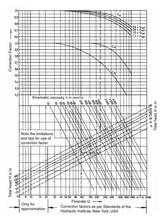
Figure 1 : Viscosity correction chart (please refer to Standard of the Hydraulic Institute, New York, for actual graph)