
Water pipe networks : maximum recommended flow velocity
Follow us on Twitter 
Question, remark ? Contact us at contact@myengineeringtools.com
1. Introduction
2. Importance of recommended velocities
3. Calculation of water flow velocity
4. Water pipe networks velocities recommendations
5. Pipe fluid velocity Excel calculator & Online Interactive Tool
1. Introduction
Recommended velocities in different water pipe networks or systems play a crucial role in ensuring the efficient and reliable transportation of water. These velocities are guidelines that engineers follow to balance factors like pressure drop, energy efficiency, and avoidance of potential issues within the network.
2. Importance of recommended velocities
Why is it important to respect maximal flow velocities in water network ?
It is important to respect recommended velocities for several reasons:
- Energy Efficiency : Excessive velocities can lead to unnecessary energy consumption due to increased friction losses in the pipes. On the other hand, velocities that are too low can cause sediment buildup and reduced flow efficiency.
- Minimized Erosion : High velocities can cause erosion of the inner pipe surfaces, leading to premature wear and tear of pipes, fittings, and valves.
- Avoiding Water Hammer : Rapid changes in velocity can lead to water hammer, a phenomenon discussed earlier, which can damage pipes and equipment.
- Pressure Loss : Extremely high velocities can lead to significant pressure drops, affecting the overall performance of the system.
- Balanced Distribution : In distribution systems, proper velocities ensure uniform water distribution to different parts of the network, preventing underflow or overflow conditions.
Top
5 Most Popular
1. Pressure drop
2. Reynolds Number
3.
Pressure drop K coefficients
4. Churchill equation
5. Moody diagram
3. Calculation of water flow velocity
How to calculate the velocity of water in pipes ?
The continuity equation defines the mean velocity \(u\) of a non-compressible fluid flowing in a full circular pipe of internal diameter \(D\) with volumetric flow rate \(\dot{Q}\):
With :
\(\dot{Q}\) = Volumetric flowrate (\(\text{m}^3/\text{s}\))
\(D\) = Pipe internal diameter (\(\text{m}\))
\(u\) = Fluid velocity in pipe (\(\text{m/s}\))
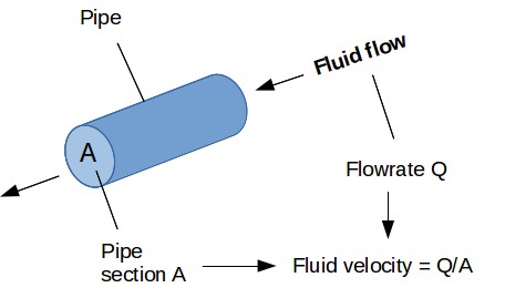
Figure 1 : Pipe fluid velocity calculation
Note that the velocity will be constant for water that is a non compressible fluid but would vary with a compressible fluid such as a gas. For a gas it is therefore necessary to slice the pipe layout in several sections in order to recalculate the velocity along the pipe.
⚡ Interactive Pipe Fluid Velocity & Sizing Calculator
Calculated Hydrodynamic Results:
📌 Plant Engineering Best Practices: Liquid Piping Design Limits
- Pump Suction Caution: Never design pump suction piping above 1.5 m/s (5.0 ft/s) for low-viscosity liquids. Excessive suction line velocity induces dynamic head drops, leading directly to pump cavitation and impeller pitting.
- Minimum Self-Cleaning Velocity: For slurry, raw water, cooling tower basins, or wastewater applications, keep minimum velocities above 0.6 – 0.9 m/s (2.0 – 3.0 ft/s) to prevent suspended solids from settling out and clogging pipes.
- Erosional Velocity Thresholds: Carbon steel piping handling untreated or saline water suffers accelerated erosion-corrosion if liquid velocities exceed 3.0 to 4.0 m/s (10 to 13 ft/s). For standard copper water tubes, ASHRAE recommends capping velocities at 1.2 – 2.4 m/s depending on service temperature.
- Water Hammer (Surge Pressure): Kinetic energy surges \(\Delta P_{surge} = \rho c \Delta u\) correlate directly with initial fluid velocity \(u\). Limiting nominal velocity below 2.5 m/s greatly dampens hydraulic shockwaves during rapid valve closures.
4. Water pipe networks velocities recommendations
What are the recommended velocities for water systems ?
| Fluid / Service Application | Recommended velocity (SI Metric) | Recommended velocity (US Customary) |
|---|---|---|
| Potable Water Distribution | 0.6 - 2 m/s | 2.0 - 6.6 ft/s |
| Fire Protection Systems | 1.5 - 3 m/s | 4.9 - 9.8 ft/s |
| Industrial Process Systems | 1 - 3 m/s | 3.3 - 9.8 ft/s |
| Irrigation Systems | 0.6 - 1.5 m/s | 2.0 - 4.9 ft/s |
| Cooling Water Systems | 1 - 3 m/s | 3.3 - 9.8 ft/s |
| Sewage and Drainage Systems | 0.3 - 1 m/s | 1.0 - 3.3 ft/s |
| Boiler feed [Hall] | 1.5 - 4.6 m/s | 4.9 - 15.1 ft/s |
| Pump suction [Hall] | 0.3 - 1.5 m/s | 1.0 - 4.9 ft/s |
| Sea and brackish water [Hall] | 1.5 - 4 m/s | 4.9 - 13.1 ft/s |
| Pump suction for wastewater [Hall] | 1 - 1.8 m/s | 3.3 - 5.9 ft/s |
| Pump discharge for wastewater [Hall] | 1 - 2.5 m/s | 3.3 - 8.2 ft/s |
| Gravity flow for wastewater [Hall] | 0.6 - 2.5 m/s | 2.0 - 8.2 ft/s |
These recommended velocities are general guidelines and may vary based on factors such as pipe material, system pressure, and specific requirements. Engineers need to consider these factors to determine the optimal velocity for a given network or system, ensuring its reliability, efficiency, and longevity.
5. Pipe fluid velocity Excel calculator
How to calculate the velocity of a fluid in a pipe ?
You can access to an Excel calculation tool in order to calculate
the velocity a fluid in a pipe, knowing the pipe diameter and the
fluid flowrate : Fluid
velocity in pipe Excel calculation tool (click here)
Warning : this calculator is provided to illustrate the concepts mentioned in this webpage, it is not intended for detail design. It is not a commercial product, no guarantee is given on the results. Please consult a reputable designer for all detail design you may need.

Sources :